Step 1: Unpacking and Environmental Preparation
1. Cleanroom Operation:
Photomasks are extremely sensitive to particulate contamination. All unpacking, inspection, and handling procedures must be performed in an ISO Class 5 / Class 6 (or equivalent Class 100 / Class 1,000) cleanroom. Even microscopic dust particles can cause pattern defects during lithography.
2. Proper Handling Techniques:
Powder-free cleanroom gloves must be worn at all times (bare hands or powdered gloves are strictly prohibited).
Use dedicated mask holders/vacuum wands or tweezers, or grip the photomask only by its absolute outer edges with both hands.
Never touch the active pattern area with hands or tools.
3. Identifying the Pattern Side (Emulsion/Chrome Side):
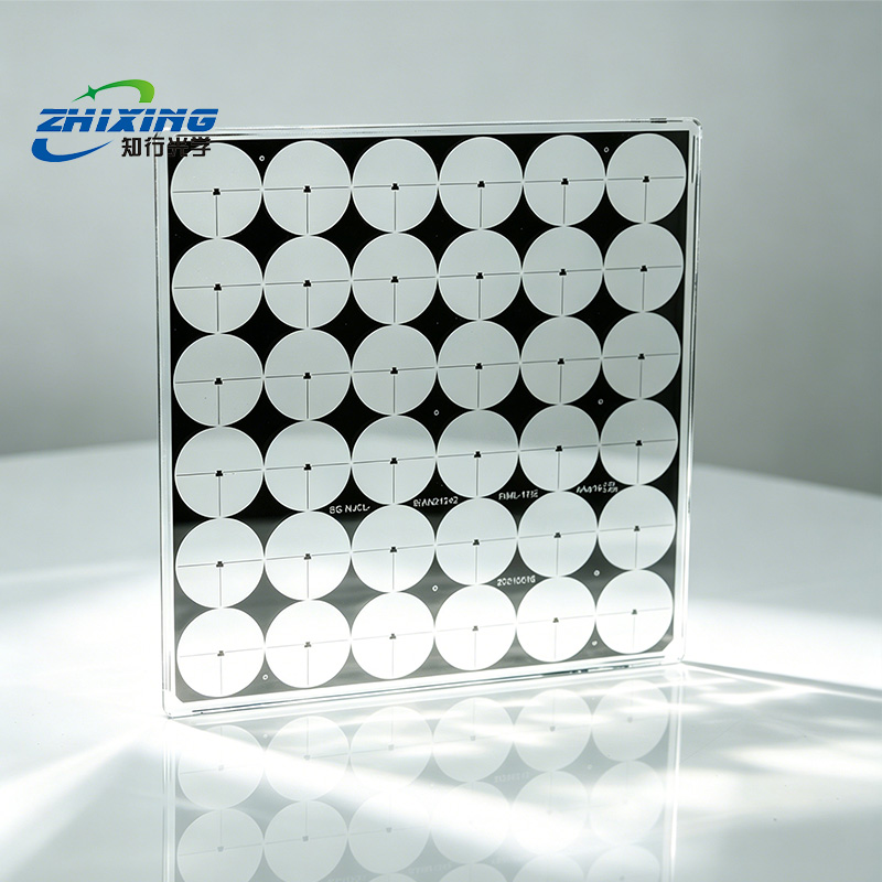
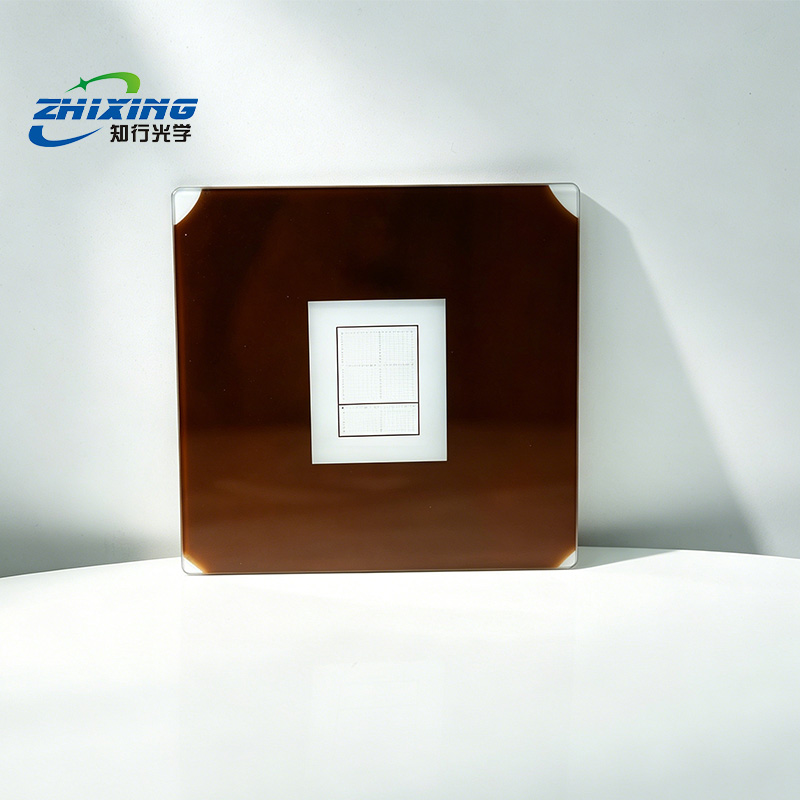
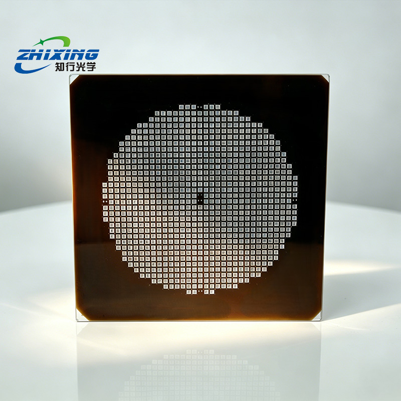
During lithography, it is critical to identify which side carries the chrome/emulsion pattern (typically characterized by higher reflectivity and a mirror-like finish). The pattern side must generally face the photoresist.
Step 2: Alignment and Installation
Select the appropriate installation and alignment method based on the type of lithography or exposure equipment:
Option A: Contact / Proximity Lithography (Common in Labs and General Industry)
Mask Loading: Place the photomask into the mask holder of the aligner and secure it via vacuum chuck or mechanical clamps.
Substrate Alignment: Place the photoresist-coated substrate (e.g., silicon wafer) on the lower stage. Using the aligner’s dual-axis microscope, adjust the fine-motion stage until the alignment marks on the substrate precisely coincide with those on the photomask.
Gap Adjustment:
Contact Mode: Bring the pattern side of the mask into direct, intimate contact with the photoresist surface to achieve maximum resolution.
Proximity Mode: Maintain a micron-scale gap between the mask and the substrate to prevent scratching the mask.
Option B: Projection / Stepper Lithography (Common in Semiconductor Mass Production)
Load the photomask into the automated reticle handling system.
The exposure system uses laser alignment sensors to automatically detect the fiducial alignment holes at the edge of the mask, locking it precisely at the focal plane of the projection optics.
Step 3: Exposure and Pattern Transfer
Parameter Setup: Based on the photosensitive wavelength of the photoresist (e.g., common I-line 365 nm, G-line 436 nm, or Deep UV) and its thickness, set the precise exposure dose or exposure time on the exposure tool.
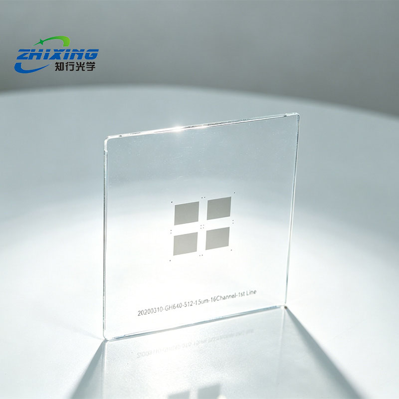
Light Transmission: Initiate exposure. UV light passes through the transparent areas of the photomask (e.g., quartz/glass substrate) to expose the photoresist, while the opaque regions (e.g., metal chrome layer) completely block the light.
Post-Processing: After exposure, remove the substrate and proceed with development. The pattern from the photomask is now successfully transferred onto the substrate.
Step 4: Unloading, Cleaning, and Storage
Prompt Unloading: Immediately unload the photomask from the equipment after exposure or batch processing is complete to prevent heat accumulation or electrostatic charge buildup from prolonged exposure to the optical path.
Purge and Inspection: Gently purge the surface with high-purity nitrogen gas to remove any adhered photoresist debris or particulates.
Safe Light-Tight Storage: Place the photomask in a dedicated anti-static protective case. Store it vertically in a yellow-light safe area (shielded from UV and sunlight) or in a dry cabinet to prevent degradation or fungal growth of the film layer.