I. Core Equipment List
| Equipment |
Function |
Key Requirements |
| Optical System Under Test (Industrial Camera / Lens / Microscope) |
Capture images of the resolution target |
Lens focuses properly with no significant distortion; camera parameters are manually adjustable. |
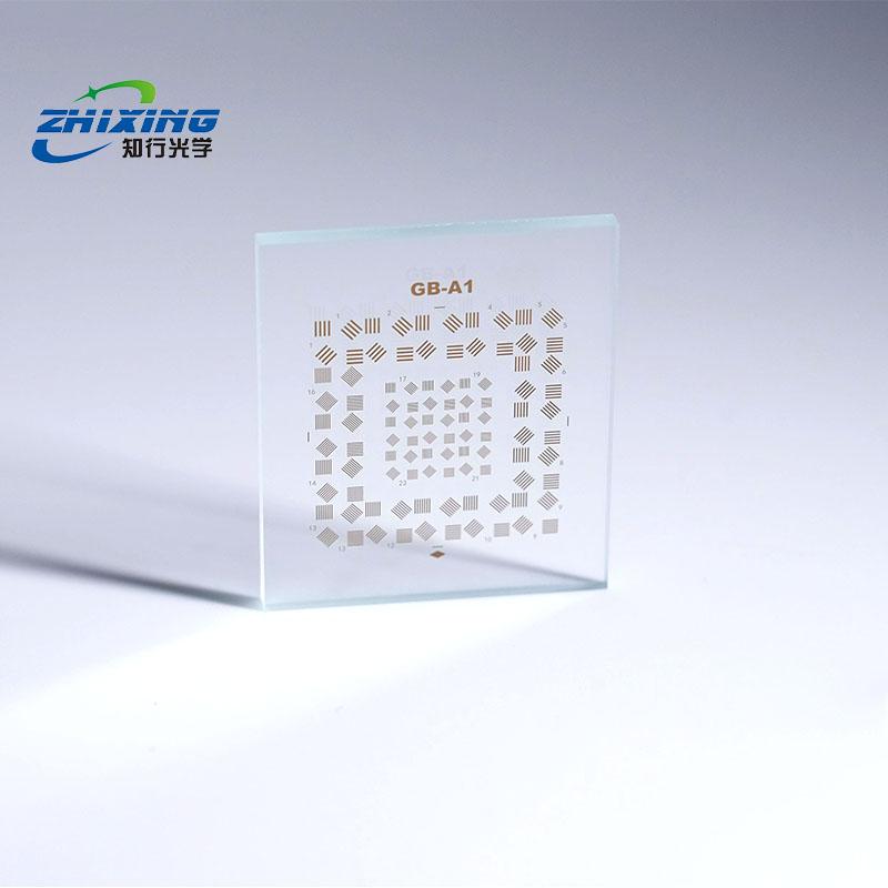
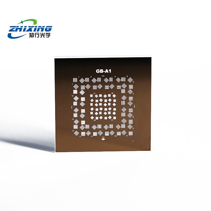
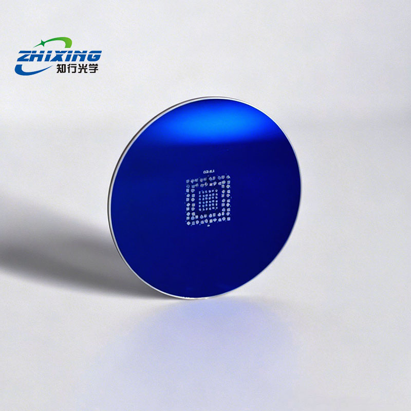
| GB Type A Resolution Target |
Test target |
Free of scratches and contamination; pattern side facing the lens. |
| Uniform Illumination Source (LED Backlight / Collimator) |
Illuminate the target |
Uniform lighting without shadows; avoid overexposure/underexposure; stable contrast. |
| Stand / Optical Bench |
Illuminate the target |
Uniform lighting without shadows; avoid overexposure/underexposure; stable contrast. |
| Image Acquisition Software (e.g., OpenCV, proprietary camera software) |
Capture and view images |
Supports live preview and raw image saving. |
II. Confirmation of Key Parameters
Target Model Matching: Select the appropriate target based on the theoretical resolution of the lens (e.g., use A2/A3 models with line widths of 10–50 µm for standard industrial lenses). Ensure the target's line width does not exceed the lens's resolution limit.
Working Distance: Position the target at the lens's specified working distance. If the lens is focusable, prioritize its optimal imaging distance.
Camera Settings: Disable auto-exposure, autofocus, and auto white balance. Manually set ISO/exposure time to ensure the target's stripes are sharp and free from motion blur.
III. Operational Procedure (with Key Step Descriptions)
Step 1: Set Up the Optical Path
Secure the Target: Place the resolution target on a clean workbench or backlight source with the pattern side facing the lens. Align the center of the target with the optical axis of the lens. The target must be perfectly perpendicular to the optical axis; verify by checking if the target edges appear parallel in the live preview. Avoid tilting the target, as this causes stripe stretching and distortion, leading to reading errors.
Adjust the Light Source: Turn on the uniform light source and illuminate the target from behind (backlighting) to ensure even brightness across the entire target, free from glare and shadows. Do not use direct overhead lighting, as it creates specular reflections that reduce stripe contrast.
Adjust Camera Position: Aim the camera/lens at the target and adjust the working distance so that the target pattern fills 70%–90% of the frame. Avoid framing too tightly to ensure full-field imaging evaluation.
Step 2: Focus and Parameter Calibration
1. Manual Focus: In the live preview, slowly adjust the lens focus ring until the fine stripes at the center of the target (e.g., Elements 23 and 24) appear sharpest. Prioritize focusing on the center of the target, then fine-tune the target position to ensure uniform sharpness across the entire field of view.
2. Adjust Exposure and Gain: Manually adjust exposure time and camera gain so that the black stripes on the target appear near pure black and the white background near pure white. Avoid overexposure (white stripes bleeding together) or underexposure (black stripes appearing gray).
3. Lock All Parameters: Once focus, exposure, and ISO are set, lock all settings to prevent parameter changes during capture from affecting results.
Step 3: Capture Standard Test Images
1. Keep the target and camera stable, and capture at least 3 images (you may slightly adjust the target angle between shots to obtain the best result).
2. Save raw images (uncompressed, without auto-sharpening) to prevent post-processing from altering stripe details.
Step 4: Read Resolution Results (Core Determination Method)
1. Inspect from Coarse to Fine: Starting from Element 1 (coarsest stripes) on the outer edge of the target, inspect sequentially toward the center. Identify the finest element where stripes in all 4 orientations (horizontal / vertical / ±45°) can be clearly resolved.
Acceptance Criteria: Boundaries between black and white stripes are distinct, with no merging or blurring. Imaging boundaries are clearly distinguishable and not fused.
Example: If stripes in all 4 orientations of Element 12 are clear, but the ±45° stripes in Element 13 begin to merge, the limiting resolution of your lens corresponds to the line width of Element 12.
2. Table Lookup & Conversion: Refer to the line width / line pair density table in the JB/T 9328 standard using the element number to obtain the specific resolution value.
Conversion Formula: Line Pair Density (lp/mm) = 1 ÷ (2 × Line Width in mm)