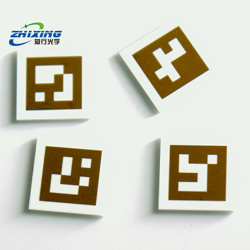
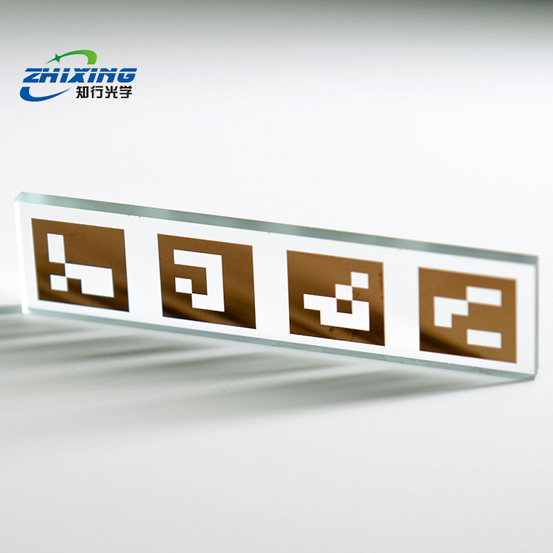
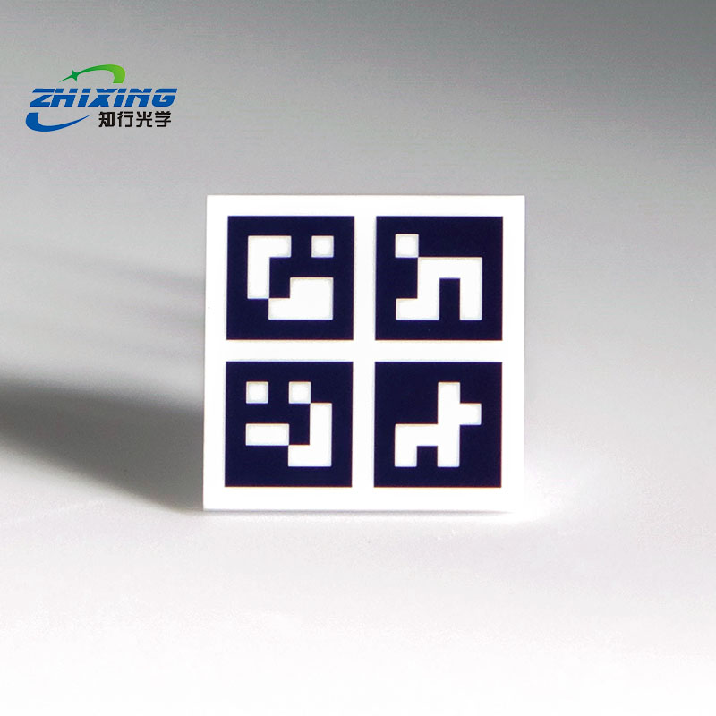
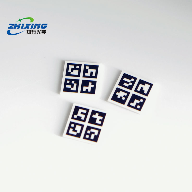
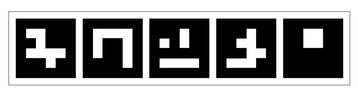
An ArUco calibration target is a digital fiducial marker system featuring unique binary-encoded IDs (dictionaries). It is widely used in computer vision (e.g., OpenCV, ROS), robotic localization, camera intrinsic calibration, and AR spatial tracking. Its core principle relies on detecting the four corners of each marker within an image to rapidly compute the relative 3D position and orientation (translation vector T and rotation matrix R) between the camera and the target.
Step 1: Environment Setup & Placement
Flatness Requirement: Mount the ArUco target on an absolutely flat surface (e.g., tempered glass plate, aluminum honeycomb panel, or a precision-machined robot end-effector). Any warping or bending will introduce errors in 3D pose estimation.
Lighting Conditions: Ensure uniform illumination across the target surface. Avoid direct specular reflections (e.g., mirror-like glare) on the black-and-white encoded areas, as pixel saturation can prevent reliable edge detection and decoding.
Distance & Viewing Angle: Position the target within the camera’s field of view. Thanks to ArUco’s high fault tolerance, the system can accurately detect markers even at significant tilt angles or with partial occlusion along the edges.
Step 2: Parameter Configuration
Before invoking OpenCV or other vision algorithms, record and input the following physical parameters of the target (typically labeled on the product packaging):
Dictionary Type: Identify which encoding library your target belongs to (e.g., DICT_4X4_50, DICT_6X6_250).
Marker Physical Size: Measure or verify the absolute physical side length of a single black-and-white square marker (unit: meters [m] or millimeters [mm]), excluding the surrounding white border. This parameter directly determines the absolute accuracy of spatial distance calculations.
Step 3: Algorithm Detection & Implementation
In mainstream computer vision frameworks (e.g., OpenCV / Python), the standard workflow is as follows:
Image Acquisition: Capture images or video streams containing the ArUco target and convert them to grayscale.
Marker Detection: Call the ArUco detection function (e.g., cv2.aruco.detectMarkers()). The algorithm automatically locates the pixel coordinates of all four outer corners for every visible marker and decodes their corresponding IDs.
Camera Calibration: If calibrating the camera, capture multiple images from various angles. Using the detected corner coordinates and known physical dimensions, compute the lens focal length, principal point, and distortion coefficients (e.g., via cv2.aruco.calibrateCameraAruco()). 。
Pose Estimation: If performing localization, provide the camera intrinsics and call the pose estimation function (e.g., cv2.aruco.estimatePoseSingleMarkers()). The system instantly outputs the 3D coordinates (X, Y, Z) and rotation angles of the target relative to the camera.
Step 4: Data Application & Output
Robot/Drone Navigation: Use the output relative coordinates to guide equipment for precise alignment with or landing on the target.
AR/VR Augmented Reality: Use the four detected corners of the ArUco marker as a reference plane to render virtual 3D objects in real time on screen.
Maintenance, Care & Customization Notes
Preserve Black-White Boundaries: ArUco relies on high contrast at black-white transitions for sub-pixel corner extraction. Do not draw, scratch, or deface the encoded area. Replace the target immediately if edges are chipped or severely worn.
Moisture & Scratch Protection: Store in a dry environment after use. Clean only with a soft cloth or air blower; never use corrosive organic solvents, as they will damage the high-precision printed coating.