Product Introduction
 A resolution target, also known as an optical resolution test chart or resolution calibration target, is a tool used to test and evaluate the resolving power of imaging systems. By incorporating resolution elements of varying spatial frequencies and placing the target in the image plane as a reference for observation, it enables assessment of an imaging system’s performance. A resolution target, also known as an optical resolution test chart or resolution calibration target, is a tool used to test and evaluate the resolving power of imaging systems. By incorporating resolution elements of varying spatial frequencies and placing the target in the image plane as a reference for observation, it enables assessment of an imaging system’s performance.
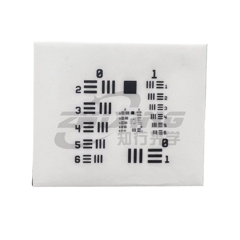
The USAF 1951 resolution target, developed by the United States Air Force in 1951 and compliant with the U.S. military standard MIL-STD-150A, is widely used for testing the resolution capabilities of optical imaging systems. It is commonly referred to as “USAF 1951,” “US Military Standard 1951,” or simply “USAF target.”
Resolution targets are primarily employed to evaluate the performance of imaging systems and to assess the image quality of various optical instruments and equipment.
These targets consist of arrays of horizontal and vertical line patterns designed to determine the resolution limit of an imaging system. Each group contains six elements (comprising alternating horizontal and vertical line pairs), and ten such groups form the complete resolution pattern. The figure on the left illustrates elements 2 and 3 from Group –2 of the resolution target.
Resolution targets utilize triplets of lines (three-line groups) to enhance the ability to detect true resolution. When excessive blurring causes overlapping lines to appear as a single inverted, seemingly sharper line, a phenomenon known as "false resolution" occurs. This can lead to misinterpretation of an optical system’s actual resolving capability, as the lines may appear resolvable when they are not. False resolution may also cause a three-line group to appear as if it contains only two lines. Because the visual difference between three lines and two lines is more easily discernible than that between five lines and four lines, using three-line groups makes it easier to identify false resolution. The accompanying diagram shows the relevant calculation formula.

|