


CN
Your current position:Home > Products > CGH Null Correctors
Loading...

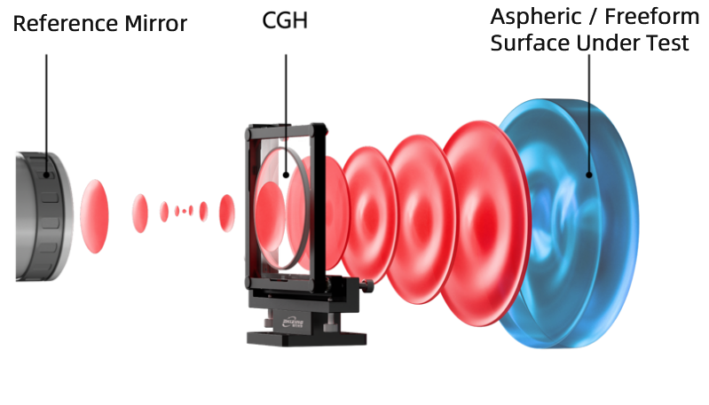
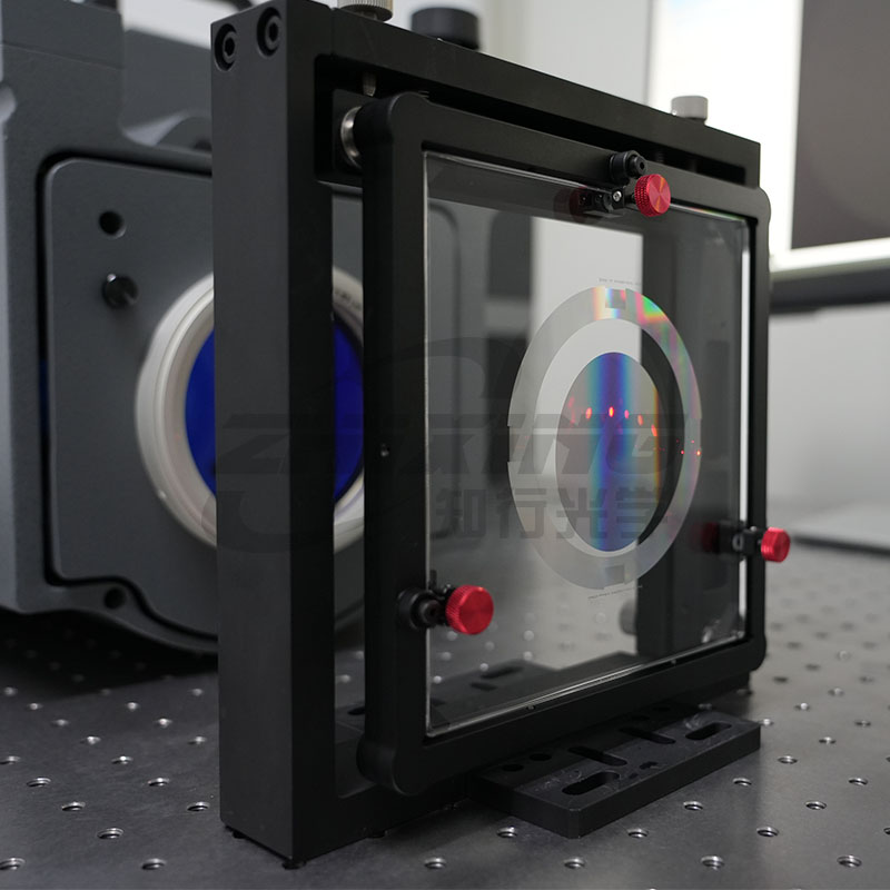
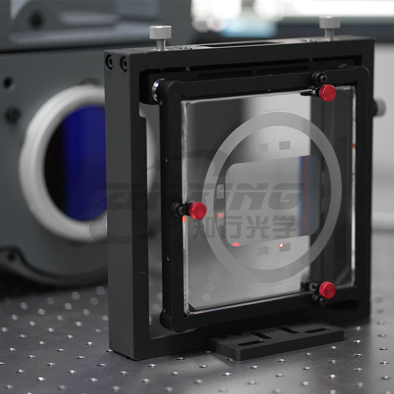
Aspheric CGH

Product Series:CGH Null Correctors

Parameter Technical Specification
Dimensions 6-inch, 9-inch, 12-inch
Metrology Accuracy Up to 1 nm RMS
Measurement Configuration Horizontal (horizontal optical axis), Vertical (vertical optical axis)
Lithography Precision 3σ < 50 nm (down to 10 nm)
Standard Lead Time 7–10 days
Fast-Track Lead Time 3 days (for urgent R&D requirements)

Conventional Aspheric Surface Testing

Conventional aspheric surface testing is primarily categorized into coaxial concave aspheric testing and coaxial convex aspheric testing.

1. Coaxial Concave Aspheric Surfaces

      The design of coaxial concave aspheric surfaces is typically classified according to the type of carrier frequency employed (categorized as tilt carrier frequency and defocus carrier frequency, used to spatially separate the desired diffracted light from stray light):

a. Ghost Image Separation via Tilt Carrier Frequency

Optical Design


  • Ghost Image Analysis


  • Wavefront Accuracy


  • Fringe Density


Ghost Image Separation via Defocus Carrier Frequency

Optical Design


  • Ghost Image Analysis


  • Wavefront Accuracy


  • Fringe Density


2. Coaxial Convex Aspheric Surfaces

      The design of coaxial convex aspheric surfaces is typically classified according to the type of interferometer reference optic employed (categorized as flat reference optics and spherical reference optics):

a. Design Based on Plane Wavefront
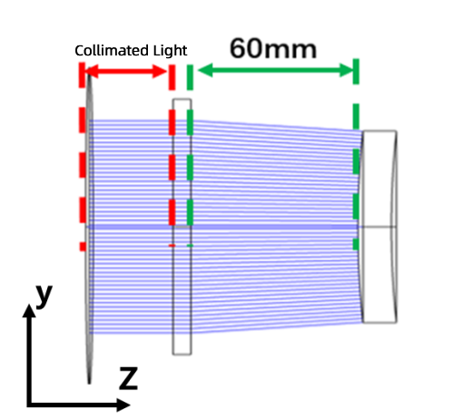
Optical Design


  • Ghost Image Analysis


  • Wavefront Accuracy


  • Fringe Density


b. Design Based on Spherical Wavefront

Optical Design


  • Ghost Image Analysis


  • Wavefront Accuracy


  • Fringe Density

Off-Axis Aspheric Surface Testing

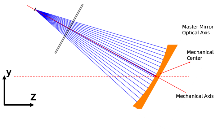
For off-axis aspheric surface testing, the component is typically aligned so that its mechanical axis coincides with the optical axis of the interferometer during the design phase, thereby facilitating on-site implementation.

Optical Design


  • Ghost Image Analysis


  • Wavefront Accuracy


  • Fringe Density


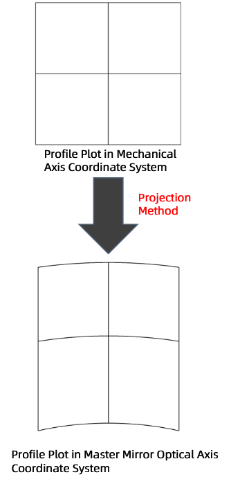
Important Note:Typically, the surface profile provided on aspheric drawings is defined in the mechanical axis coordinate system. However, optical design software (e.g., Zemax) requires the input profile to be defined in the coordinate system of the parent asphere's optical axis. Therefore, a projection method must be employed to transform the profile from the mechanical coordinate system into the parent asphere's optical axis coordinate system.


Alignment of Off-Axis Three-Mirror Anastigmat Systems

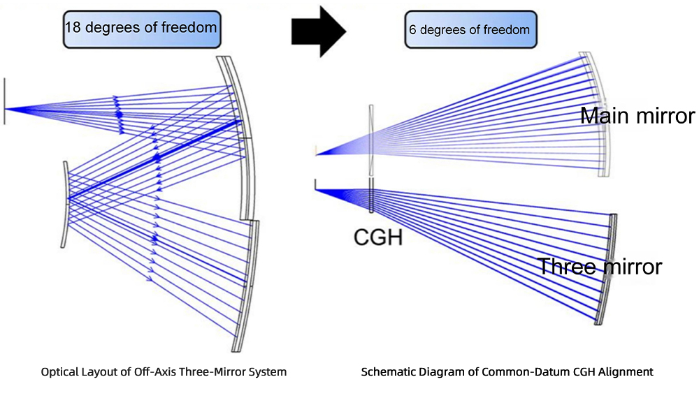
For the alignment of off-axis three-mirror anastigmat (TMA) systems, a common-datum CGH referencing both the primary and tertiary mirrors is employed to reduce the traditionally complex alignment process to a straightforward surface figure testing procedure.


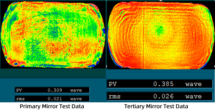
Alignment Results of the Primary and Tertiary Mirrors

Incomplete Wavefront Testing

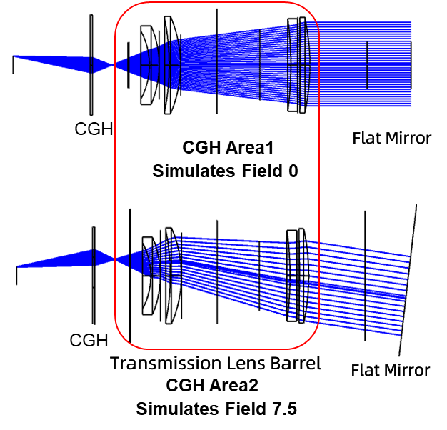
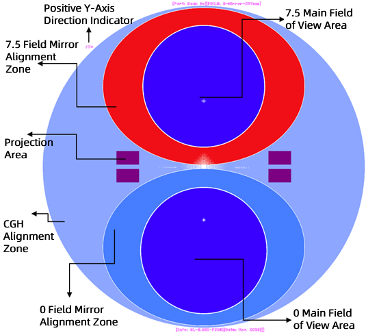
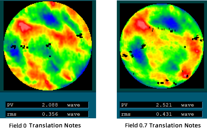
For incomplete optical systems, a CGH is employed to transform the partial assembly into a testable imaging configuration. Through multi-field transmitted wavefront testing during subsystem alignment, the future performance of the subsystem within the complete system can be predicted, thereby reducing the overall integration and alignment cycle in later stages.


Optical Design


Schematic Diagram of CGH Pattern Functionality


Contact Us